Yaesu FT-101 HF Transceiver Web Page
Presented by Fox Tango International.
Yaesu Musen Co. FT-101
(Yaesu Wireless Co.)
FT-101 Modules
|
FT-101 Version |
VFO |
REG |
HF-IF |
LO-IF |
AUDIO |
RF |
MOD |
RECTIFIER |
BLANKER |
PROCESSOR |
|
FT-101 MK-1 (Early) |
PB1078A |
PB1076A |
Part of |
None |
||||||
|
FT-101 MK-2 (Late) |
PB1056 |
PB1183 |
PB1189 |
PB1184 |
PB1076B |
PB1182 |
None |
|||
|
FT-101B (Early) |
PB1056 |
PB1180 |
PB1183B |
PB1076B |
PB1292 |
None |
||||
|
FT-101B (Late) |
PB1056 |
PB1180B |
PB1183B |
PB1181B |
PB1184A |
PB1076B |
PB1292 |
None |
||
|
FT-101E/EE/EX (Early) |
PB1056 |
PB1314A |
PB1180B |
PB1183B |
PB1181B |
PB1184A |
PB1076B |
PB1292 |
PB1494 |
|
|
FT-101E/EE/EX (Mid) |
PB1056 |
PB1314A |
PB1180B |
PB1183B |
PB1181B |
PB1184A |
PB1076B |
PB1292 |
PB1534 |
|
|
FT-101E/EE/EX (Late) |
PB1056 |
PB1574A |
PB1180B |
PB1183C |
PB1181B |
PB1184A |
PB1076B |
PB1534A |
||
|
FT-101F/FE/FX (All) |
PB1056 |
PB1180B |
PB1183C |
PB1315B |
PB1181B |
PB1184A |
PB1076B |
PB1534A |
|
FT-101 Audio Boards PB-1081B, PB-1081C, PB-1189, PB-1315A~Z |
|
|
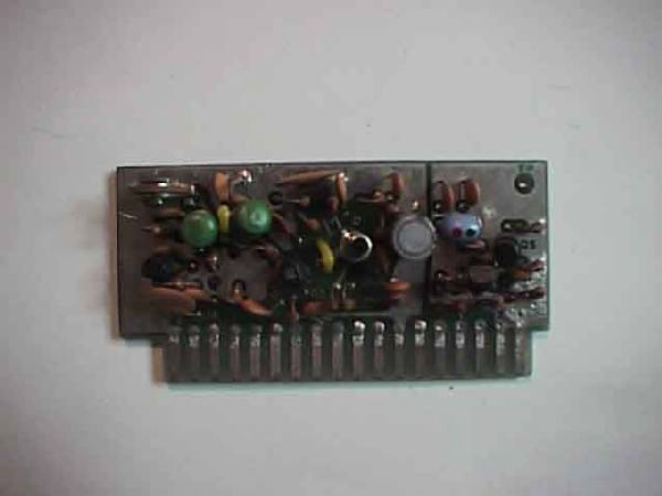
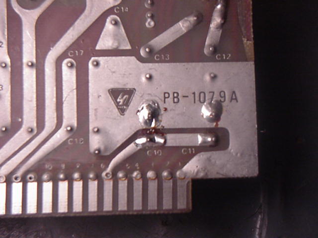
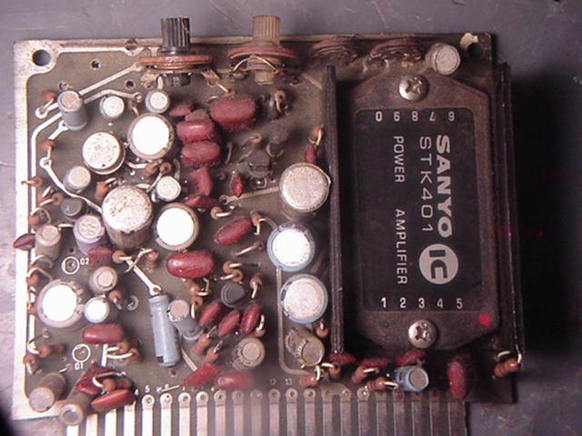
This Module contains microphone amplifier, Audio Amplifier, Vox and CW side tone. One can easily note the difference from PB1081C which was used in the late production FT-101 transceivers which came with the large SANYO STK-401 audio amplifier chip and PB-1315A/B audio unit used in the newer FT-101E and F model transceivers. Very Early FT-101 (MK-1) used an early audio board PB-1081B it has two (PNP 2SB463) transistors in push pull. As noted below you will see Q-10 and Q-11 on PB1081B. Upgraded FT-101 (MK-1) transceivers used audio board PB-1081C and then later models FT-101 (MK-2) transceivers used PB-1189. With the introduction of the FT-101B the audio board changed again using audio board PB-1315 in (Early) FT-101B production. All of these audio modules (except for PB-1081B) used the large Sanyo STK-401 audio chip which was often a source of failure in the audio circuit due to oscillation. It wasn't until the FT-101B(2) late production we are introduced to the improved audio unit PB-1315A using the smaller AN-214 (4.4 watt) integrated circuit audio power amplifier chip. Yaesu used the AN-214 audio chip in many of it's amateur transceivers including the famous FRG-7 communications receiver. The AN-214 proved to be very reliable and the use of PB-1315A/B continued until the end 101 production. It's interesting to note while the FT-101 series of transceivers basically looked the same for all the years they remained in production. They were often fondly referred to by many as the (VW) Volkswagen of amateur radio. While they basically keep the same look from the outside, a keen eye could note the improvements being made by the factory under the (bonnet) hood of this finely tuned machine. Such is the case when looking at the Audio modules below.
|
|
|
|
 Audio Board FT-101 (MK-1) Early PB-1081C Audio board FT-101 (MK-2) PB-1189 - No pix Both boards use the large Sanyo STK-401 Audio Amplifier chip. |
|
|
Au Used in the FT-101E and F models transceivers. This board replaced earlier versions and used the smaller 4.4 watt AN-214 9 pin single in line package, integrated circuit audio power amplifier chip. Should you ever need to replace an AN-214 a suitable replacement is the NTE-1058 as noted below. The AN214 was used in most of Yaesu amateur products throughout the 1970s. |
|
|
 NTE1058 Linear AF power output IC 4.4W and audio preamp. Equiv. To AN214P. Case style 9 pin SIP. |
|
High
Frequency IF Modules PB-1183 &
PB-1180 (early)
|
|
|
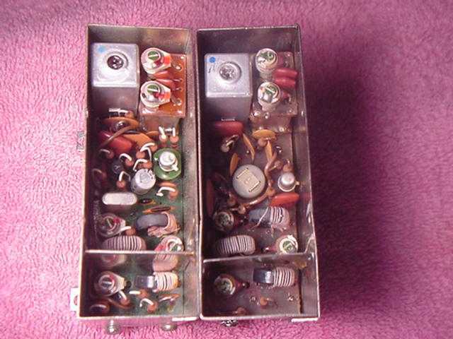
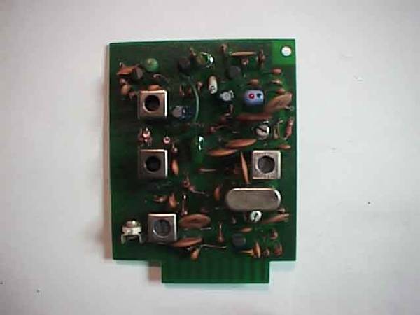
High Frequency IF Module, Unit PB-1180B IF Unit: Transmit 1st mixer & Receiver 2nd mixer.
What you are looking at here is the early PB-1083C (Right) and PB-1180 (Left) side by site. The early board is on your right. You will see clearly on PB-1180 to your left, there is a 6360 KHz crystal that is absent on the early board. This is part of a 6.36 MHz trap going out the circuit board to L-32 via Pin #14. It is generally assumed you can not put a PB-1180B into a very early FT-101 which has PB-1084, this is true. However you can put PB-1180B into an early unit if you cut the ground on Pin #14 under your early FT-101. If you try to upgrade your early radio with PB1180B you will have no signal path as the ground on pin #14 of the early transceiver will short out your I.F signal path until the ground is removed from plug in socket MJ(2) Pin #14 which holds the mixer unit under the early FT-101 transceiver. It can be done successfully and a newer High Frequency unit can be used in an early FT-101 by doing this step. |
|
|
|
|
|
PB1183/B/C did not have the noise blanker on this board. |
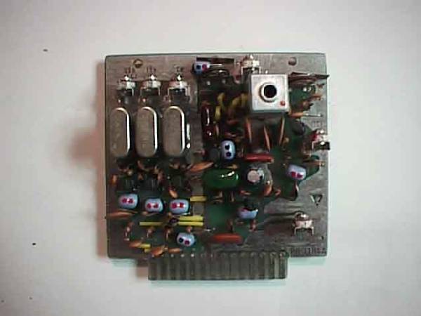
Low Frequency LO-IF Unit PB1183/B/C & PB1080A
Low Frequency IF Module PB1183B/C this module contains the low frequency IF amplifier, SSB and CW crystal filters, detector and AGC/S meter circuits. The 3180 KHz signal from the noise blanker is fed through this unit and the SSB/CW Filters through the Low Frequency IF Unit. In transmit mode, the IF signal is applied to high frequency I.F. unit from pin #10. NOTE: YOU CAN NOT TAKE PB-1183 and put it into an early FT-101 which uses a PB-1080A, the reason you can not update an early transceiver with this board is that the very early FT-101 had the noise blanker circuit on PB-1080A. Later models in the series FT-101/B/E/F had a plug in noise blanker boards such as PB-1582B shown below. In the case of the original late model FT-101 there was a noise blanker which included the crystal control board (PB-1182) this unit was installed on top of the VFO and the interconnection of this module were wired directly without using plug-in socket. |
|
with noise blanker on LO-IF |
|
|
XF-30C 600 Hz CW Filter Center Freq 3179.3 KHz
|
Filters in your FT-101 On the low frequency I.F. unit you will often find the XF-30A or XF-32A SSB filters, XF-30C 600 Hz CW filter or the XF-30B 6 KHz wide AM filter. |
|
XF-32A SSB filter 8 pole 2.4 KHz filter, center frequency 3180 KHz |
|
|
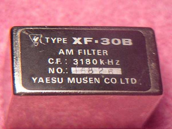
XF-30B AM Filter 6 KHz wide, center frequency 3180 KHz |
|
|
|
|
|
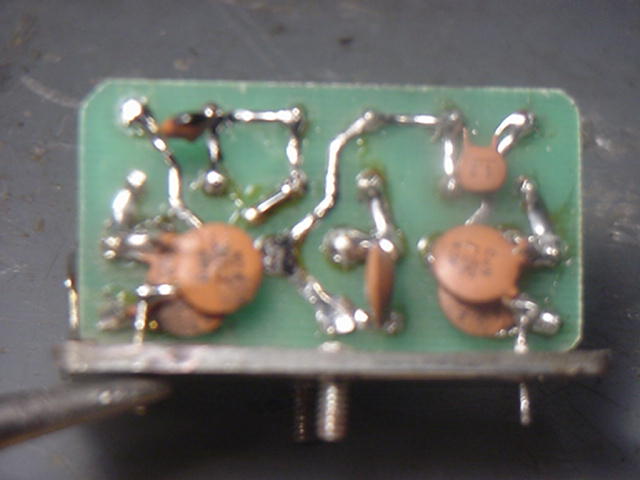
Here we can see an XF-30A 6 pole 2.4 KHz SSB filter on a Yaesu speech processor unit. The XF-30A was originally used in the I.F. for the FT-101, it is a six pole filter. Later the manufacturer went to the XF-32A filter, it is an eight pole filter. Both filters had a center frequency of 3.180 MHz and a 2.4 KHz band width. |
|
|
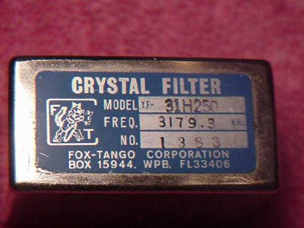
Fox Tango Optional narrow 250 Hz CW filter. Model YF 31-H250 |
|
Modulator Unit PB1184 & PB1078A
Modulator Unit PB-1184A. The carrier oscillator & modulator unit has separate oscillators for USB, LSB, modes while CW & AM use the same oscillator crystal. Except for a very few minor changes on this board, the modulator unit is one of the few boards which virtually remained the same through out the entire production of the transceiver. There is really very little difference between a PB-1078A and a PB-1184A and there should be no reason what so ever that the two can not be interchanged, if needed.
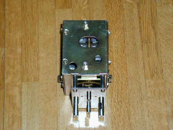
Noise Blanker Unit PB1292, PB1182, PB1582
 Noise Blanker PB-1582B receives 3180
KHz to the noise blanker unit.
Very early FT-101 series transceivers had the noise blanker circuit on
PB-1080A. Later models in the series
FT-101/B/E/F had a plug in noise blanker boards such as PB1182, PB1292 and
PB-1582. Lots of changes to the noise blanker circuit over the years, enough to write
another book so we will reserve comment on it until a later date.
Noise Blanker PB-1582B receives 3180
KHz to the noise blanker unit.
Very early FT-101 series transceivers had the noise blanker circuit on
PB-1080A. Later models in the series
FT-101/B/E/F had a plug in noise blanker boards such as PB1182, PB1292 and
PB-1582. Lots of changes to the noise blanker circuit over the years, enough to write
another book so we will reserve comment on it until a later date.
RF Unit
(Front end) PB-1077B and PB-1181C
Early PB-1077B with relay.
 The module contains the receiver RF amplifier, receiver 1st
mixer, transmitter 2nd mixer and heterodyne oscillator circuit. The base
circuit of the receiver mixer Q3 on this board is disconnected in transmit by a
small relay (RL1) to avoid the lowering the Q of the receiver 1st mixer circuit
while in transmit mode.
The module contains the receiver RF amplifier, receiver 1st
mixer, transmitter 2nd mixer and heterodyne oscillator circuit. The base
circuit of the receiver mixer Q3 on this board is disconnected in transmit by a
small relay (RL1) to avoid the lowering the Q of the receiver 1st mixer circuit
while in transmit mode.
 RF Unit, PB1181C. Contains RF amplifier, 1st mixer, Tx 2nd mixer and
heterodyne Oscillator section. This module contains the receiver RF
amplifier, receiver 1st mixer, transmitter 2nd mixer and heterodyne oscillator
circuit. NOTE: PB-1181 can replace PB1077B in
earlier FT-101 transceivers, without any problem. The early HF Unit
PB-1077B had a small relay (RL1) on the board, the relay would be activated in
transmit mode so as not to lower the "Q" of the circuit in Tx mode. The
mechanical relay was quickly replaced by a diode switch to avoid the lowering
the "Q" of the circuit. The later board PB1181C is far superior to the original design with the addition of a local oscillator buffer (Q5) 2SC373, diode
switching, and (Q2) FET 2SK19 for the Receive 1st Mixer. The RF amplifier Q1 also
saw some change during production from it's original 3SK39 to a 3SK40 in later
model transceivers. It was later recommended by Fox Tango members to replace the 3SK40
with a 3N201 MOSFET that was internally diode protected from static discharge on
the antenna and less likely to blow out. An added advantage of the 3N201 was
slightly higher receiver gain. Due to the fact that the 3N201 is no longer
available a the suggested replacement part is an NTE-454, N-channel, Dual Gate MOSFET.
RF Unit, PB1181C. Contains RF amplifier, 1st mixer, Tx 2nd mixer and
heterodyne Oscillator section. This module contains the receiver RF
amplifier, receiver 1st mixer, transmitter 2nd mixer and heterodyne oscillator
circuit. NOTE: PB-1181 can replace PB1077B in
earlier FT-101 transceivers, without any problem. The early HF Unit
PB-1077B had a small relay (RL1) on the board, the relay would be activated in
transmit mode so as not to lower the "Q" of the circuit in Tx mode. The
mechanical relay was quickly replaced by a diode switch to avoid the lowering
the "Q" of the circuit. The later board PB1181C is far superior to the original design with the addition of a local oscillator buffer (Q5) 2SC373, diode
switching, and (Q2) FET 2SK19 for the Receive 1st Mixer. The RF amplifier Q1 also
saw some change during production from it's original 3SK39 to a 3SK40 in later
model transceivers. It was later recommended by Fox Tango members to replace the 3SK40
with a 3N201 MOSFET that was internally diode protected from static discharge on
the antenna and less likely to blow out. An added advantage of the 3N201 was
slightly higher receiver gain. Due to the fact that the 3N201 is no longer
available a the suggested replacement part is an NTE-454, N-channel, Dual Gate MOSFET.
N-CHANNEL MOSFET (UPDATE) 3/06
Improved replacement for Yaesu FT-101 1st RF Amplifier now available
 The 'FT -MOSFET' is an
improved replacement for the Yaesu FT-101 first RF amplifier and the Yaesu
FT-301 Mixer. The MOSFET increases RX sensitivity. Its inputs are
diode protected and it has a very low noise characteristic. Reports from
Club members have been overwhelming enthusiastic. Several Club members
have reported that in the FT-101's with the 3SK39 (3SK40 in the newer
models) as the first RF amplifier, the RX sensitivity at highest signal levels
remains the same or may even be diminish by an S unit or two when compared to the
improved replacement MOSFET. Each rig is slightly different, but in all
cases the MOSFET increases the linearity characteristic and brings up low level
signals before inaudible. Installation could not be easier and involves
removing the 3SK39 / 3SK40 and inserting the 'FT FET' in the socket of PB-1181B,
FT-101B/E/F models. For more information on the Club
"FT-FET" click here.
The 'FT -MOSFET' is an
improved replacement for the Yaesu FT-101 first RF amplifier and the Yaesu
FT-301 Mixer. The MOSFET increases RX sensitivity. Its inputs are
diode protected and it has a very low noise characteristic. Reports from
Club members have been overwhelming enthusiastic. Several Club members
have reported that in the FT-101's with the 3SK39 (3SK40 in the newer
models) as the first RF amplifier, the RX sensitivity at highest signal levels
remains the same or may even be diminish by an S unit or two when compared to the
improved replacement MOSFET. Each rig is slightly different, but in all
cases the MOSFET increases the linearity characteristic and brings up low level
signals before inaudible. Installation could not be easier and involves
removing the 3SK39 / 3SK40 and inserting the 'FT FET' in the socket of PB-1181B,
FT-101B/E/F models. For more information on the Club
"FT-FET" click here.

Click here to see the NTE-454 data sheet for this device.
Power Regulator Modules
Through out the production of the FT-101 series of transceivers there were many changes to the power supply regulator module. However they all basically did the same thing but the circuitry was improved. reaching the same means to the end result. The DC 13.6 volts from the rectifier unit is filter on this board and produces a stable 6 volt DC supply. Regulated voltage is provided to the clarifier and VFO circuits for stability from this board. The regulator board also has a transmit bias control on this board. A (-100 volts) negative one hundred volts supply sets the operating bias to the final amplifier tubes at approximately -50 volts. And The bias for the 12BY7A is also supplied from this board. (-20 volts) negative twenty volts on receive and (-3.5 volts) three and a half volts on the driver tube during transmit.

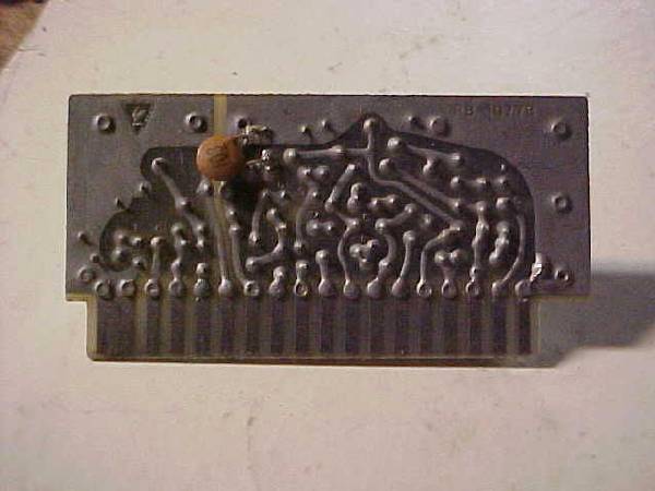
 Power Regulator Unit
PB-1079A in the very early transceivers used two NPN transistors to
provide a stable 6 volt DC supply voltage need for the rest of the transceiver
and produced 100 KHz and 25 KHz marker signals. This unit is easily
identifiable by it's large heat sink on the regulator transistor Q5 (2SC697) and the
large 100 KHz HC-13U crystal used in it's marker generator.
Power Regulator Unit
PB-1079A in the very early transceivers used two NPN transistors to
provide a stable 6 volt DC supply voltage need for the rest of the transceiver
and produced 100 KHz and 25 KHz marker signals. This unit is easily
identifiable by it's large heat sink on the regulator transistor Q5 (2SC697) and the
large 100 KHz HC-13U crystal used in it's marker generator.

 Less often seen is PB1314,
this board
can be found in the early FT-101B series transceivers. More
often then not you will see PB1314A as shown below with an (MFC-6030A) integrated circuit
being used in place of the two bi-polar NPN transistors for the 6 volt regulator
circuit..
Less often seen is PB1314,
this board
can be found in the early FT-101B series transceivers. More
often then not you will see PB1314A as shown below with an (MFC-6030A) integrated circuit
being used in place of the two bi-polar NPN transistors for the 6 volt regulator
circuit..
 PB1314A often seen in the FT-101B Late
production and early FT-101E transceivers. It uses a voltage regulator (I.C.) integrated circuit in place of the two bipolar
transistors seen on earlier units to produce a regulated 6 volt DC supply.
This is one of the areas where we see the most change going on with this board
throughout the years of the transceivers production. The integrated
circuit type MFC-6030A provided an
extremely stable 6 vdc supply for the VFO and clarifier. However through
the years the MFC-6030A has become a source
of failure on these regulator units and it can be difficult at best to find.
This unit can also be identified easily because it has
PB1314A often seen in the FT-101B Late
production and early FT-101E transceivers. It uses a voltage regulator (I.C.) integrated circuit in place of the two bipolar
transistors seen on earlier units to produce a regulated 6 volt DC supply.
This is one of the areas where we see the most change going on with this board
throughout the years of the transceivers production. The integrated
circuit type MFC-6030A provided an
extremely stable 6 vdc supply for the VFO and clarifier. However through
the years the MFC-6030A has become a source
of failure on these regulator units and it can be difficult at best to find.
This unit can also be identified easily because it has
the large 100
KHz HC-13U
crystal and the MFC-6020 integrated circuit multivibrator which
generates a marker signal every 25 KHz. The integrated circuits type
MFC-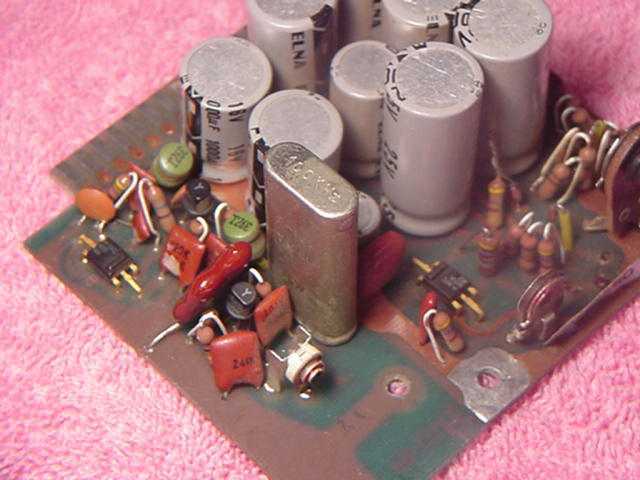 6030, MFC-6032
and MFC6034A look identical. See:
Fox Tango Candy Store for
MFC6030A
6030, MFC-6032
and MFC6034A look identical. See:
Fox Tango Candy Store for
MFC6030A


MFC6030A
MFC6034A
Ic(max)
200ma
200ma
Output V (nominal)
19V
11V
Drop-out V (max)
3.0
3.0
Pwr Dissipation
1.0 Watt
1.0 Watt
Supply V (max)
38V
22V
Min Out adj V
1.2V
???
Max Out adj V
37
???
MFC6030A,6032A,6033A, and 6034A, are all basically the same. They can be
interchanged for FT-101 use.
If you are in need
of a replacement regulator, check with the club candy store for purchase
of a replacement.
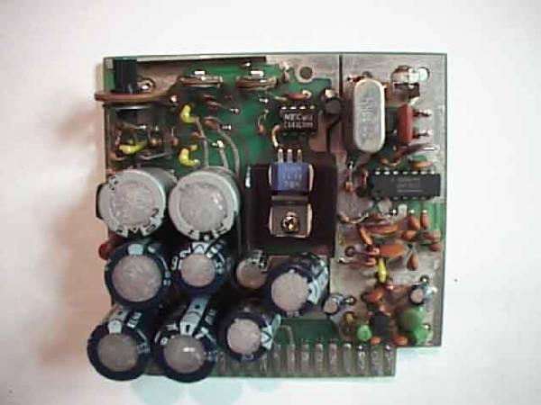 Power Regulator Board PB1547A and B was the final and best power supply circuit board.
It sported a regulator circuit comprised of Q1, uPC141C, and Q2 (2SA634) for an
extremely stable 6 volt DC supply which is fed to various circuits from pin #13
of it's board. This board also had the latest marker signal generator
using a 3200 KHz crystal frequency signal that is divided into 100 KHz and 25
KHz marker signals which was then fed to the receiver antenna circuit.
Power Regulator Board PB1547A and B was the final and best power supply circuit board.
It sported a regulator circuit comprised of Q1, uPC141C, and Q2 (2SA634) for an
extremely stable 6 volt DC supply which is fed to various circuits from pin #13
of it's board. This board also had the latest marker signal generator
using a 3200 KHz crystal frequency signal that is divided into 100 KHz and 25
KHz marker signals which was then fed to the receiver antenna circuit.
If you have an item of interest you would like to see added to the Fox Tango Web Site
Email Suggestions or Corrections to: Web Master Fox Tango International
Carol L. Maher W4CLM
(c) Fox Tango International, 2004. All rights reserved
Thank You For Visiting Fox Tango FT-101 Web Page


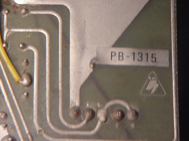
 dio Unit PB-1315A